Concidering Graph Tech Ghost in Fly Deluxe

Discussions of every Fly in every variation including Deluxe, Classic, Mojo, Artist, Supreme, Stealth, Concert/Bronze, and custom Flys
User avatar
vjmanzo
Site Admin
Posts: 2003
Joined: Sat Feb 02, 2019 12:35 pm
Location: New York, NY
Contact:

Re: Concidering Graph Tech Ghost in Fly Deluxe

Post by vjmanzo »

mmmguitar wrote: Mon Nov 06, 2023 3:23 pm I think we'll be writing it together. ;)
♥️♥️♥️♥️♥️
Gregsaab
Full Member
Posts: 188
Joined: Sun Feb 20, 2022 10:07 pm

Re: Concidering Graph Tech Ghost in Fly Deluxe

Post by Gregsaab »

Ordered both of those parts. I guess that’ll make us Ghost writers 8-)
1998 Deluxe in Dusty Black
1999 Deluxe in Emerald Green
2011 Mojo in Transparent Red [sold]
Gregsaab
Full Member
Posts: 188
Joined: Sun Feb 20, 2022 10:07 pm

Re: Concidering Graph Tech Ghost in Fly Deluxe

Post by Gregsaab »

8-)
Attachments
0E6D7296-C06B-4BF1-A419-A2E7F7472142.jpeg
1998 Deluxe in Dusty Black
1999 Deluxe in Emerald Green
2011 Mojo in Transparent Red [sold]
User avatar
mmmguitar
Forum Veteran
Posts: 1179
Joined: Tue Oct 01, 2019 1:25 am
Contact:

Re: Concidering Graph Tech Ghost in Fly Deluxe

Post by mmmguitar »

@Gregsaab, I don’t know whether you intend to enlarge the pre-existing channel the piezo signal wire passes through from the spring cavity to the control cavity or drill in a different spot, but Graph Tech specifies a minimum 5/16” bit to give their connectors sufficient berth to be fed through.
Summary of the Parker Guitars speculator market from 2020 onward: https://en.wikipedia.org/wiki/Greater_fool_theory
Gregsaab
Full Member
Posts: 188
Joined: Sun Feb 20, 2022 10:07 pm

Re: Concidering Graph Tech Ghost in Fly Deluxe

Post by Gregsaab »

mmmguitar wrote: Thu Nov 09, 2023 7:39 pm @Gregsaab, I don’t know whether you intend to enlarge the pre-existing channel the piezo signal wire passes through from the spring cavity to the control cavity or drill in a different spot, but Graph Tech specifies a minimum 5/16” bit to give their connectors sufficient berth to be fed through.
Probably just enlarge the existing…unless there is a good reason to make a new one.
1998 Deluxe in Dusty Black
1999 Deluxe in Emerald Green
2011 Mojo in Transparent Red [sold]
Gregsaab
Full Member
Posts: 188
Joined: Sun Feb 20, 2022 10:07 pm

Re: Concidering Graph Tech Ghost in Fly Deluxe

Post by Gregsaab »

The summing boards and connector cables have arrived at last.
1998 Deluxe in Dusty Black
1999 Deluxe in Emerald Green
2011 Mojo in Transparent Red [sold]
Gregsaab
Full Member
Posts: 188
Joined: Sun Feb 20, 2022 10:07 pm

Re: Concidering Graph Tech Ghost in Fly Deluxe

Post by Gregsaab »

I should now have some time to work on this project.

Are the steps along these lines:
1. Remove old saddles
2. Drill larger channels in each saddle location so as to be able to route the Ghost’s connectors
Edit: I reread previous response - need to enlarge channel betwixt spring & main cavity
3. Connect each saddle to summing boards
4. Remove wires from summing board output connector
5. Solder wires from Step 5 directly onto the Fishman board

For #1, will I need to desolder these? Where are they soldered to
For #2, will I need to remove spring?
1998 Deluxe in Dusty Black
1999 Deluxe in Emerald Green
2011 Mojo in Transparent Red [sold]
User avatar
mmmguitar
Forum Veteran
Posts: 1179
Joined: Tue Oct 01, 2019 1:25 am
Contact:

Re: Concidering Graph Tech Ghost in Fly Deluxe

Post by mmmguitar »

Gregsaab wrote: Fri Dec 01, 2023 1:00 pm For #1, will I need to desolder these? Where are they soldered to
For #2, will I need to remove spring?
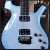
1. The Fishman element lead wires are soldered to the underside of the bridge, which acts as a summing board from which another wire travels via a drilled channel into the main cavity, where it is soldered to the input of the Powerchip:
elements.JPG
Above, you can see the little solder blobs where I removed the Fishman elements. As you can infer from the photo,

2. Yes; removing the spring is helpful for getting at the underside of the bridge with your soldering iron tip. You may even find you need to remove the bridge entirely to get a good working angle. Being as my soldering station is temp-adjustable, I just use a chisel tip and crank it up so that all the solder joints quickly liquefy. I then used either a screwdriver tip or thin needle nose pliers to pull the loose element leads out of the blobs before they re-hardened.

Next are two shots of the enlarged channel which allowed the Graph Tech elements to pass from the spring cavity to the control cavity:
channel 1.JPG
channel 2.JPG
Your other steps seem straightforward enough - You won't be certain until you're in the thick of it :D

One important point I nearly forgot is to remind you to repurpose the old summed piezo lead wire soldered to the underside of the bridge by making it your bridge ground wire (relocate it from the Powerchip input to a common ground connection). UPDATE: This recommendation ended up causing unnecessary headaches for Gregsaab; due to my not knowing his wire was a shielded single-conductor which bridged signal and ground connections at each end. Make certain of whether your wire is pulling double duty!
Summary of the Parker Guitars speculator market from 2020 onward: https://en.wikipedia.org/wiki/Greater_fool_theory
Gregsaab
Full Member
Posts: 188
Joined: Sun Feb 20, 2022 10:07 pm

Re: Concidering Graph Tech Ghost in Fly Deluxe

Post by Gregsaab »

Thank you for that.
Out of curiosity, why can’t we re-use that existing ‘summing board’ that you just showed?
1998 Deluxe in Dusty Black
1999 Deluxe in Emerald Green
2011 Mojo in Transparent Red [sold]
User avatar
mmmguitar
Forum Veteran
Posts: 1179
Joined: Tue Oct 01, 2019 1:25 am
Contact:

Re: Concidering Graph Tech Ghost in Fly Deluxe

Post by mmmguitar »

Gregsaab wrote: Fri Dec 01, 2023 3:00 pm Thank you for that.
Out of curiosity, why can’t we re-use that existing ‘summing board’ that you just showed?
Hopefully someone will correct me if I'm misremembering: The Fishman circuit uses the underside of the bridge as a combination summing board and string ground as a consequence of the saddles themselves being conductive metal - Whereas the graphite composite material of the Ghost saddles isn't serving to ground the strings (that's seemingly achieved through each saddle having a dedicated ground wire for the element, with the string ball ends' seating in the bridge being their primary grounding point). You're not using the Graph Tech preamp, but its design utilizes designated signal and ground inputs for their saddles' pin connections which renders the "summing board" aspect of the Fly bridge redundant.

You could use the underside of the bridge as a summing point for the saddle ground wires - But it would be a pointless amount of extra work to separate the lead and ground wires of the elements between cavities, when they're designed for a dual pin summing board at the preamp itself.
Summary of the Parker Guitars speculator market from 2020 onward: https://en.wikipedia.org/wiki/Greater_fool_theory
Gregsaab
Full Member
Posts: 188
Joined: Sun Feb 20, 2022 10:07 pm

Re: Concidering Graph Tech Ghost in Fly Deluxe

Post by Gregsaab »

If the Ghost ground wires could be soldered to a different common ground, it seems like it could be less work to piggy back off of the existing summing. That would remove need to expand the drilled passage way etc.
1998 Deluxe in Dusty Black
1999 Deluxe in Emerald Green
2011 Mojo in Transparent Red [sold]
User avatar
mmmguitar
Forum Veteran
Posts: 1179
Joined: Tue Oct 01, 2019 1:25 am
Contact:

Re: Concidering Graph Tech Ghost in Fly Deluxe

Post by mmmguitar »

Gregsaab wrote: Fri Dec 01, 2023 4:36 pm If the Ghost ground wires could be soldered to a different common ground, it seems like it could be less work to piggy back off of the existing summing. That would remove need to expand the drilled passage way etc.
I agree. But as I elaborated on the previous page, working with the individual Ghost wires is far more tedious than drilling the existing channel larger (which is why the official retrofit guide from Parker specifies the summing board and pulling the pin connector off the summing wire(s)). I’ve done it both ways; and assure you that one is the lesser evil.
Summary of the Parker Guitars speculator market from 2020 onward: https://en.wikipedia.org/wiki/Greater_fool_theory
Gregsaab
Full Member
Posts: 188
Joined: Sun Feb 20, 2022 10:07 pm

Re: Concidering Graph Tech Ghost in Fly Deluxe

Post by Gregsaab »

After several weeks of our family being ravaged by the flu, I’m breaking ground :lol:

Drilling a larger hole from the main cavity to spring cavity seems a little scary to me. Not exactly sure how I would even have the clearance to do so with a normal drill.

Would it be crazy to do this instead: leave the ground wire in there and run a hot wire through as well. I would then leave the Graphtech summing board in the spring cavity and just solder that output to the existing ground wire and the new hot lead? Then tuck the summing board next to/behind T-bar.
Attachments
BDF0327B-B2ED-4D8A-97B7-7901EA33823F.jpeg
60E99C86-9BEF-40B7-8518-9532E47327AA.jpeg
1998 Deluxe in Dusty Black
1999 Deluxe in Emerald Green
2011 Mojo in Transparent Red [sold]
Gregsaab
Full Member
Posts: 188
Joined: Sun Feb 20, 2022 10:07 pm

Re: Concidering Graph Tech Ghost in Fly Deluxe

Post by Gregsaab »

Also, is this the correct orientation for the T-bar?
Attachments
2C0DE319-1BAF-4136-AF3C-5880C3597F9B.jpeg
1998 Deluxe in Dusty Black
1999 Deluxe in Emerald Green
2011 Mojo in Transparent Red [sold]
User avatar
mmmguitar
Forum Veteran
Posts: 1179
Joined: Tue Oct 01, 2019 1:25 am
Contact:

Re: Concidering Graph Tech Ghost in Fly Deluxe

Post by mmmguitar »

Gregsaab wrote: Sat Dec 09, 2023 8:28 pm Also, is this the correct orientation for the T-bar?
I think that’s the orientation I have mine in (note the “UP” I wrote on mine in the above photo of the tangerine Fly).

Your idea to have the piezo leads summed in the spring cavity will work, provided you have enough room to accommodate the six pairs of wires and the spring. If the spring ends up moving the piezo lead wires around on the course of flexing, that noise may end up being microphonically amplified by the Powerchip.

Whenever I’ve enlarged the piezo wire channel to accommodate the Graph Tech connectors, I just hold the drill upside down and angle the bit downward from the spring cavity toward the control cavity. Though I have a longer bit for such a job, I haven’t needed it for the Flys.
Summary of the Parker Guitars speculator market from 2020 onward: https://en.wikipedia.org/wiki/Greater_fool_theory
Gregsaab
Full Member
Posts: 188
Joined: Sun Feb 20, 2022 10:07 pm

Re: Concidering Graph Tech Ghost in Fly Deluxe

Post by Gregsaab »

I may attempt to drill, I would prefer to keep all of the wires out of the spring cavity. Though, if I do keep them in there, I’ll heat shrink them and keep it as tidy as possible.

The green lead mounted directly next to the gnd on the board is positive, correct?
1998 Deluxe in Dusty Black
1999 Deluxe in Emerald Green
2011 Mojo in Transparent Red [sold]
Gregsaab
Full Member
Posts: 188
Joined: Sun Feb 20, 2022 10:07 pm

Re: Concidering Graph Tech Ghost in Fly Deluxe

Post by Gregsaab »

Is this where the white and black leads from the summing board should ultimately connect to?

Also, you mentioned repurposing the factory summing board:
One important point I nearly forgot is to remind you to repurpose the old summed piezo lead wire soldered to the underside of the bridge by making it your bridge ground wire (relocate it from the Powerchip input to a common ground connection).
Could you elaborate a bit on that? What else would be soldered to the summing board aside from the common ground? Why is that needed if each saddle has its own ground? Or is that to ground the strings? If so, is there anything else that needs to be done to accomplish that?
Attachments
CC93D549-02B7-42AD-A898-B438CB8E59C6.jpeg
1998 Deluxe in Dusty Black
1999 Deluxe in Emerald Green
2011 Mojo in Transparent Red [sold]
User avatar
mmmguitar
Forum Veteran
Posts: 1179
Joined: Tue Oct 01, 2019 1:25 am
Contact:

Re: Concidering Graph Tech Ghost in Fly Deluxe

Post by mmmguitar »

Gregsaab wrote: Sun Dec 10, 2023 12:09 am The green lead mounted directly next to the gnd on the board is positive, correct?
I think green was always coded as "ground" in the USM Flys.

I've added some text to your photos that I'm hoping will help clear this up:

board.jpeg
channel.jpeg
One end of that black wire is currently soldered to the "hot" signal input of the Powerchip, and the other end is soldered to the underside of the bridge. When you unsolder the Fishman element leads from the underside of the bridge, leave that black wire soldered to the bridge; because it will become the new string ground. Unsolder the Powerchip end of that black wire and relocate it to one of the other grounding points to convert it to a functional string ground. Note that you'll have to first snake the black wire out of the channel between the spring and control cavities if you plan to enlarge it with a drill bit, before feeding it back through to ground it.

The white/black color coding of your summing wires depends on how you orient the connector at the summing board: Whichever pin the blue Ghost saddle wires are summed to (I use black) should be soldered to the green wire at the Powerchip board; with whatever wire the gray/silver wires of the Ghost saddles are summed to (I use white) replacing the black wire connection to the right of it on the board. In case you happen to get the pin orientation wrong (which will present itself as a wonky "out of phase" sound), you can just flip where the dual connector plugs in to the summing board to reverse the "hot" and "ground."
Summary of the Parker Guitars speculator market from 2020 onward: https://en.wikipedia.org/wiki/Greater_fool_theory
Gregsaab
Full Member
Posts: 188
Joined: Sun Feb 20, 2022 10:07 pm

Re: Concidering Graph Tech Ghost in Fly Deluxe

Post by Gregsaab »

Whichever pin the blue Ghost saddle wires are summed to (I use black) should be soldered to the green wire at the Powerchip board; with whatever wire the
All of the Ghost wires are black/white.
with whatever wire the gray/silver wires of the Ghost saddles are summed to (I use white) replacing the black wire connection to the right of it on the board.
So should the corresponding summed Ghost output would be wired to the two connections here, right?
361214B0-74CE-46B1-957F-E0017D7DA44D.jpeg
I think green was always coded as "ground" in the USM Flys.
The spot on the Powerchip where the black lead from the current summing board is soldered is labeled ‘GND’. This is what is confusing me.
7F2EBF0A-F7DD-4941-B169-8A2A1245809C.jpeg
1998 Deluxe in Dusty Black
1999 Deluxe in Emerald Green
2011 Mojo in Transparent Red [sold]
Gregsaab
Full Member
Posts: 188
Joined: Sun Feb 20, 2022 10:07 pm

Re: Concidering Graph Tech Ghost in Fly Deluxe

Post by Gregsaab »

Trying to match up my guitar with the schematics in the FAQ:
F4104420-52BF-48FA-A71C-83A4E18EDAAF.jpeg
This doesn’t seem to correspond as the orientation of the wires is different.
B10AF094-326A-4E6E-9313-8BF36FB3CC38.jpeg
This correlates a bit more, but only has the ground on the corner, doesn’t have the connection where my green wire is soldered. Note that in this case, my black wire would be the ground, not the green?

Edit:
Ah, is this diagram from the underside of the powerchip? I didn’t think it matched my Mojo’s because I didn’t see that on-board potentiometer.
6972E76A-3430-441F-99E7-5BA7FA31A5BA.jpeg
1998 Deluxe in Dusty Black
1999 Deluxe in Emerald Green
2011 Mojo in Transparent Red [sold]
Post Reply